Raspberry PI Bare Metal Vol 2 : UART #
In my previous blog post, I discussed the basics of setting up a bare-bones Raspberry Pi environment and toggleling GPIO pins. In this post, we will explore how to set up UART (Universal Asynchronous Receiver/Transmitter) communication on the Raspberry Pi.
If you haven’t read the previous post, I recommend checking it out first to understand the foundational concepts of bare-metal programming on the Raspberry Pi. [Link]
If you dont know what UART is, please refer to this link or read Mastering Embedded Linux Programming book by Chris Simmonds which has helped me to understand UART in depth (not sponsored).
Setting Up UART (Universal Asynchronous Receiver/Transmitter) #
UART is a serial communication protocol that allows for asynchronous data transmission between devices. The Raspberry Pi has built-in UART capabilities that can be accessed through its GPIO pins.
There are multiple UART peripherals available on the Raspberry Pi, but we will focus on the primary mini UART for this example. Mini UART is 16650-compatible and provides a simple way to communicate with other devices using serial communication. mini UART is a secondary low throughput UART intended to be used as a console. I have not hammered it but I guess it can easily achieve baud rates more than 115200 bps. I will be limiting the usage to 115200 bps for my experiments. Good part of this mini UART is it shares its clock with the system core clock, so no need to fiddle with separate clock settings and it is by default enabled by the GPU firmware. So we dont have to do the MBox magic to enable it.
Code Implementation #
To set up UART communication on the Raspberry Pi, we need to configure the GPIO pins for UART functionality and initialize the UART peripheral. Below is a simple example of how to achieve this in a bare-metal environment.
.equ   MPIDR_AFFINITY_MASK, 0x3
.equ   PERIPHERAL_BASE,   0x3F000000

.equ   AUX_ENABLES,       (PERIPHERAL_BASE + 0x215004)
.equ   AUX_MU_IO_REG,     (PERIPHERAL_BASE + 0x215040)
.equ   AUX_MU_IER_REG,    (PERIPHERAL_BASE + 0x215044)
.equ   AUX_MU_LCR_REG,    (PERIPHERAL_BASE + 0x21504C)
.equ   AUX_MU_MCR_REG,    (PERIPHERAL_BASE + 0x215050)
.equ   AUX_MU_LSR_REG,    (PERIPHERAL_BASE + 0x215054)
.equ   AUX_MU_CNTL_REG,   (PERIPHERAL_BASE + 0x215060)
.equ   AUX_MU_BAUD_REG,   (PERIPHERAL_BASE + 0x215068)
.equ   GPFSEL1,           (PERIPHERAL_BASE + 0x200004)
.equ   GPPUPPDN0,         (PERIPHERAL_BASE + 0x2000E4)

.section ".data"

hello_msg:
    .asciz "Hello from UART!\n"

.section ".text.boot"
.global _start

_start:
    mrs     x1, mpidr_el1
    and     x1, x1, #MPIDR_AFFINITY_MASK
    cbnz    x1, park_core

park_core:
    wfe
    b       park_core

uart_setup:
    ldr     x1, =_start
    mov     sp, x1

    bl      uart_init
    ldr     x0, =hello_msg

write_loop:
    ldrb    w1, [x0], #1
    cbz     w1, main_loop
    bl      uart_send_char
    b       write_loop

main_loop:
    wfe
    b       main_loop

uart_init:
    ldr     x1, =AUX_ENABLES
    mov     w2, #1
    str     w2, [x1]
    ldr     x1, =AUX_MU_CNTL_REG
    str     wzr, [x1]
    ldr     x1, =AUX_MU_LCR_REG
    mov     w2, #3
    str     w2, [x1]
    ldr     x1, =AUX_MU_MCR_REG
    str     wzr, [x1]
    ldr     x1, =AUX_MU_IER_REG
    str     wzr, [x1]
    ldr     x1, =AUX_MU_BAUD_REG
    mov     w2, #541
    str     w2, [x1]
    ldr     x1, =GPPUPPDN0
    str     wzr, [x1]
    ldr     x1, =GPFSEL1
    ldr     w2, [x1]
    bic     w2, w2, #(7 << 12)
    orr     w2, w2, #(2 << 12)
    bic     w2, w2, #(7 << 15)
    orr     w2, w2, #(2 << 15)
    str     w2, [x1]
    ldr     x1, =AUX_MU_CNTL_REG
    mov     w2, #3
    str     w2, [x1]
    ret

uart_send_char:
    ldr     x2, =AUX_MU_LSR_REG
    ldr     w3, [x2]
    tst     w3, #0x20
    beq     uart_send_char
    ldr     x2, =AUX_MU_IO_REG
    strb    w1, [x2]
    ret
Explanation of the Code #
Lot of the code is already explained in my previous blog post. Here I will focus on the UART specific parts.
- UART Initialization: The
uart_initfunction configures the UART peripheral by enabling it, setting the data format (8 bits, no parity, 1 stop bit), and configuring the baud rate to 115200 bps. It also sets up the GPIO pins for UART functionality.
uart_init:
    ldr     x1, =AUX_ENABLES      // Enable mini UART
    mov     w2, #1
    str     w2, [x1]              // Write to AUX_ENABLES
    ldr     x1, =AUX_MU_CNTL_REG  // Disable transmitter and receiver during configuration
    str     wzr, [x1]              // Write 0 to AUX_MU_CNTL_REG
    ldr     x1, =AUX_MU_LCR_REG    // Set data format
    mov     w2, #3                // 8 bits, no parity, 1 stop bit
    str     w2, [x1]              // Write to AUX_MU_LCR_REG
    ldr     x1, =AUX_MU_MCR_REG   // Modem control
    str     wzr, [x1]             // Write 0 to AUX_MU_MCR_REG
    ldr     x1, =AUX_MU_IER_REG   // Disable interrupts
    str     wzr, [x1]             // Write 0 to AUX_MU_IER_REG
    ldr     x1, =AUX_MU_BAUD_REG  // Set baud rate
    mov     w2, #541            // For 115200 bps at 500MHz core clock
    str     w2, [x1]              // Write to AUX_MU_BAUD_REG
    ldr     x1, =GPPUPPDN0        // Disable pull-up/down on GPIO pins
    str     wzr, [x1]             // Write 0 to GPPUPPDN0
    ldr     x1, =GPFSEL1          // Configure GPIO pins 14 and 15 for UART
    ldr     w2, [x1]
    bic     w2, w2, #(7 << 12)    // Clear bits for GPIO14
    orr     w2, w2, #(2 << 12)    // Set ALT5 for GPIO14 (TXD)
    bic     w2, w2, #(7 << 15)
    orr     w2, w2, #(2 << 15)    // Set ALT5 for GPIO15 (RXD)
    str     w2, [x1]
    ldr     x1, =AUX_MU_CNTL_REG  // Enable transmitter and receiver
    mov     w2, #3
    str     w2, [x1]              // Write to AUX_MU_CNTL_REG
    ret
The mini UART is configured using Auxiliary AUX_* registers. The information about these registers can be found in the BCM2835 ARM Peripherals documentation.
The relevant part is register address definitions for Auxiliary Mini UART and GPIO configuration:
Auxiliary Peripherals Register Map #
The documentation provides address of 0x7E00 0000 as peripheral base address. But in Raspberry Pi 2 and Zero 2W, the base address is 0x3F00 0000. So we need to add an offset of 0x21 5000 to all peripheral addresses.
(offset = 0x3F21 5000)
| Address | Register Name | Description | Size |
|---|---|---|---|
| 0x3F21 5000 | AUX_IRQ | Auxiliary Interrupt status | 3 |
| 0x3F21 5004 | AUX_ENABLES | Auxiliary enables | 3 |
| 0x3F21 5040 | AUX_MU_IO_REG | Mini Uart I/O Data | 8 |
| 0x3F21 5044 | AUX_MU_IER_REG | Mini Uart Interrupt Enable | 8 |
| 0x3F21 5048 | AUX_MU_IIR_REG | Mini Uart Interrupt Identify | 8 |
| 0x3F21 504C | AUX_MU_LCR_REG | Mini Uart Line Control | 8 |
| 0x3F21 5050 | AUX_MU_MCR_REG | Mini Uart Modem Control | 8 |
| 0x3F21 5054 | AUX_MU_LSR_REG | Mini Uart Line Status | 8 |
| 0x3F21 5058 | AUX_MU_MSR_REG | Mini Uart Modem Status | 8 |
| 0x3F21 505C | AUX_MU_SCRATCH | Mini Uart Scratch | 8 |
| 0x3F21 5060 | AUX_MU_CNTL_REG | Mini Uart Extra Control | 8 |
| 0x3F21 5064 | AUX_MU_STAT_REG | Mini Uart Extra Status | 32 |
| 0x3F21 5068 | AUX_MU_BAUD_REG | Mini Uart Baudrate | 16 |
Size 3 indicates 3 bits are used but the register is 32 bits wide. All other bits need to be written as zero.
Lets start with the AUX_ENABLES register which is used to enable the mini UART.
AUX_ENABLES Register (AUXENB) #
The AUX_ENABLES register is used to enable the three auxiliary modules: UART, SPI1, and SPI2.
| Bit(s) | Field Name | Description | Type | Reset |
|---|---|---|---|---|
| 31:3 | Reserved | Write zero, read as don’t care | - | - |
| 2 | SPI2 enable | If set the SPI 2 module is enabled. If clear the SPI 2 module is disabled. That also disables any SPI 2 module register access | R/W | 0 |
| 1 | SPI 1 enable | If set the SPI 1 module is enabled. If clear the SPI 1 module is disabled. That also disables any SPI 1 module register access | R/W | 0 |
| 0 | Mini UART enable | If set the mini UART is enabled. The UART will immediately start receiving data, especially if the UART1_RX line is low. If clear the mini UART is disabled. That also disables any mini UART register access | R/W | 0 |
As you can see in the code above , we enable the mini UART by writing 1 to the AUX_ENABLES register.
AUX_MU_CNTL_REG Register (Mini UART Extra Control) #
| Bit(s) | Field Name | Description | Type | Reset |
|---|---|---|---|---|
| 31:8 | Reserved | Write zero, read as don’t care | - | - |
| 7 | CTS assert level | This bit allows one to invert the CTS auto flow operation polarity. If set the CTS auto flow assert level is low. If clear the CTS auto flow assert level is high | R/W | 0 |
| 6 | RTS assert level | This bit allows one to invert the RTS auto flow operation polarity. If set the RTS auto flow assert level is low. If clear the RTS auto flow assert level is high | R/W | 0 |
| 5:4 | RTS AUTO flow level | These two bits specify at what receiver FIFO level the RTS line is de-asserted in auto-flow mode. 00: De-assert RTS when the receive FIFO has 3 empty spaces left. 01: De-assert RTS when the receive FIFO has 2 empty spaces left. 10: De-assert RTS when the receive FIFO has 1 empty space left. 11: De-assert RTS when the receive FIFO has 4 empty spaces left | R/W | 0 |
| 3 | Enable transmit Auto flow-control using CTS | If this bit is set the transmitter will stop if the CTS line is de-asserted. If this bit is clear the transmitter will ignore the status of the CTS line | R/W | 0 |
| 2 | Enable receive Auto flow-control using RTS | If this bit is set the RTS line will de-assert if the receive FIFO reaches its ‘auto flow’ level. In fact the RTS line will behave as an RTR (Ready To Receive) line. If this bit is clear the RTS line is controlled by the AUX_MU_MCR_REG register bit 1 | R/W | 0 |
| 1 | Transmitter enable | If this bit is set the mini UART transmitter is enabled. If this bit is clear the mini UART transmitter is disabled | R/W | 1 |
| 0 | Receiver enable | If this bit is set the mini UART receiver is enabled. If this bit is clear the mini UART receiver is disabled | R/W | 1 |
AUX_MU_LCR_REG Register (Mini UART Line Control) #
The AUX_MU_LCR_REG register controls the line data format and gives access to the baudrate register.
| Bit(s) | Field Name | Description | Type | Reset |
|---|---|---|---|---|
| 31:8 | Reserved | Write zero, read as don’t care | - | - |
| 7 | DLAB access | If set the first to Mini UART register give access the the Baudrate register. During operation this bit must be cleared | R/W | 0 |
| 6 | Break | If set high the UART1_TX line is pulled low continuously. If held for at least 12 bits times that will indicate a break condition | R/W | 0 |
| 5:1 | Reserved | Write zero, read as don’t care. Some of these bits have functions in a 16550 compatible UART but are ignored here | - | - |
| 0 | Data size | If clear the UART works in 7-bit mode. If set the UART works in 8-bit mode | R/W | 0 |
In our code, we set bit 0 to 1 to enable 8-bit mode for data transmission.
AUX_MU_MCR_REG Register (Mini UART Modem Control) #
The AUX_MU_MCR_REG register controls the ‘modem’ signals.
| Bit(s) | Field Name | Description | Type | Reset |
|---|---|---|---|---|
| 31:8 | Reserved | Write zero, read as don’t care | - | - |
| 7:2 | Reserved | Write zero, read as don’t care. Some of these bits have functions in a 16550 compatible UART but are ignored here | - | - |
| 1 | RTS | If clear the UART1_RTS line is high. If set the UART1_RTS line is low. This bit is ignored if the RTS is used for auto-flow control. See the Mini Uart Extra Control register description | R/W | 0 |
| 0 | Reserved | Write zero, read as don’t care. This bit has a function in a 16550 compatible UART but is ignored here | - | - |
AUX_MU_IER_REG Register (Mini UART Interrupt Enable) #
The AUX_MU_IER_REG register is used to enable/disable interrupts.
| Bit(s) | Field Name | Description | Type | Reset |
|---|---|---|---|---|
| 31:8 | Reserved | Write zero, read as don’t care | - | - |
| 7:2 | Reserved | Write zero, read as don’t care | - | - |
| 1 | Enable transmit interrupts | If this bit is set the interrupt line is asserted whenever the transmit FIFO is empty. If this bit is clear no transmit interrupts are generated | R/W | 0 |
| 0 | Enable receive interrupts | If this bit is set the interrupt line is asserted whenever the receive FIFO holds at least 1 byte. If this bit is clear no receive interrupts are generated | R/W | 0 |
AUX_MU_BAUD_REG Register (Mini UART Baudrate) #
The AUX_MU_BAUD_REG register allows you to set the baud rate. The mini UART uses 8-times oversampling. The baudrate can be calculated from:
baudrate = system_clock_freq / ((baudrate_reg + 1) * 8)
Rearranging to solve for baudrate_reg:
baudrate_reg = (system_clock_freq / (8 * baudrate)) - 1
For our case with a 500MHz system clock and desired 115200 baud rate:
baudrate_reg = (500000000 / (8 * 115200)) - 1 = 542.5 - 1 = 541.5
Rounding to the nearest whole number gives us 541.
If you have 250MHz core clock, you can use 271 as the baud rate register value.
NOTE: I have set the frequency of the core clock to 500MHz but usually it is 250MHz. So the baud rate register value may vary based on your core clock frequency. You can do it by setting the appropriate value in the config.txt file on the SD card. See Overclocking section in this link.
GPIO Configuration #
GPIO pins 14 and 15 need to be configured for UART functionality:
- GPIO14: TXD (Transmit Data) - Set to ALT5 function
- GPIO15: RXD (Receive Data) - Set to ALT5 function
The GPFSEL1 register controls the function select for GPIO pins 10-19. Each GPIO pin uses 3 bits:
- Bits 12-14: GPIO14 function select
- Bits 15-17: GPIO15 function select
Setting these to 010 (binary) selects ALT5 function for UART. This is already explained in my previous blog posts Link.
- Sending Data: The
uart_send_charfunction waits until the UART is ready to transmit data and then sends a single character.
uart_send_char:
    ldr     x2, =AUX_MU_LSR_REG
    ldr     w3, [x2]
    tst     w3, #0x20
    beq     uart_send_char
    ldr     x2, =AUX_MU_IO_REG
    strb    w1, [x2]
    ret
AUX_MU_LSR_REG Register (Mini UART Line Status) #
The AUX_MU_LSR_REG register shows the data status of the mini UART.
| Bit(s) | Field Name | Description | Type | Reset |
|---|---|---|---|---|
| 31:8 | Reserved | Write zero, read as don’t care | - | - |
| 7 | Reserved | Write zero, read as don’t care. This bit has a function in a 16550 compatible UART but is ignored here | - | 0 |
| 6 | Transmitter idle | This bit is set if the transmit FIFO is empty and the transmitter is idle (finished shifting out the last bit) | R | 1 |
| 5 | Transmitter empty | This bit is set if the transmit FIFO can accept at least one byte | R | 0 |
| 4:2 | Reserved | Write zero, read as don’t care. Some of these bits have functions in a 16550 compatible UART but are ignored here | - | - |
| 1 | Receiver Overrun | This bit is set if there was a receiver overrun. That is: one or more characters arrived whilst the receive FIFO was full. The newly arrived characters have been discarded. This bit is cleared each time this register is read. To do a non-destructive read of this overrun bit use the Mini Uart Extra Status register | R/C | 0 |
| 0 | Data ready | This bit is set if the receive FIFO holds at least 1 symbol | R | 0 |
In our uart_send_char function, we check bit 5 (Transmitter empty) to ensure the transmit FIFO can accept data before writing to the AUX_MU_IO_REG register. The AUX_MU_IO_REG register is primarily used to write data to and read data from the UART FIFOs. If the DLAB bit in the line control register is set, this register gives access to the LS 8 bits of the baud rate.
AUX_MU_IO_REG Register (Mini UART I/O Data) #
The AUX_MU_IO_REG register is primarily used to write data to and read data from the UART FIFOs. If the DLAB bit in the line control register is set, this register gives access to the LS 8 bits of the baud rate.
| Bit(s) | Field Name | Description | Type | Reset |
|---|---|---|---|---|
| 31:8 | Reserved | Write zero, read as don’t care | - | - |
| 7:0 | LS 8 bits Baudrate | Access to the LS 8 bits of the 16-bit baudrate register (Only if bit 7 of the line control register (DLAB bit) is set) | R/W | 0 |
| 7:0 | Transmit data | Data written is put in the transmit FIFO (Provided it is not full) (Only if bit 7 of the line control register (DLAB bit) is clear) | W | 0 |
| 7:0 | Receive data | Data read is taken from the receive FIFO (Provided it is not empty) (Only if bit 7 of the line control register (DLAB bit) is clear) | R | 0 |
- Main Loop: The main loop sends the string “Hello from UART!” character by character over the UART interface.
Conclusion #
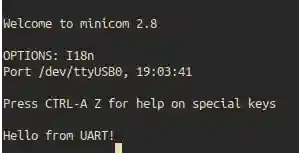
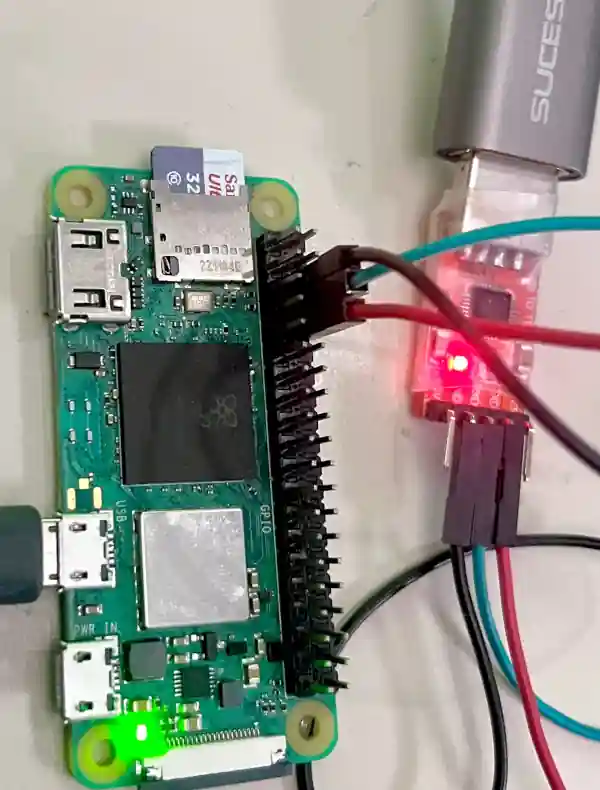
The code was successfully tested using same procedure described in my previous blog post Link. You can connect a USB to TTL serial adapter to the Raspberry Pi’s GPIO pins 14 (TXD) and 15 (RXD) to receive the transmitted data as shown in the photo below. Make sure to set the serial terminal software (like PuTTY or minicom) to 115200 bps, 8 data bits, no parity, and 1 stop bit. I am using minicom in Ubuntu 22.04 for this purpose.
And the output looks like below: