Introduction Of A Packet Journey Through TCP/IP #
Recently I read a paper [1] that detailed the journey of a network packet through the TCP/IP stack. It is a great read for anyone interested in networking and embedded systems but its not very detailed on how the packet actually gets from the application layer down to the physical layer and back up again. It brought back some memories from my research assistant days when I worked on an Linux kernel TCP/IP stack and tried to understand how packets flow through the stack. I was working on the randomization algorithm for ephemeral ports and IP Identification in the IP layer to improve security for DNS spoofing attacks. I remember spending hours tracing packets through the stack using tools like tcpdump, wireshark, strace, netfilter hooksto see how the packets were being processed.At the same I was also working on my Raspberry Pi Bare Metal in assembly blog and found out that getting WiFi working was not a trivial task.
I realized I never really understood the full journey of a packet through the TCP/IP stack, But you might never need to know this level of detail unless you are working on low-level networking code or developing network protocols. However, I thought it would be interesting to document the journey of a packet through the TCP/IP stack as it is a mystery to many developers and engineers.
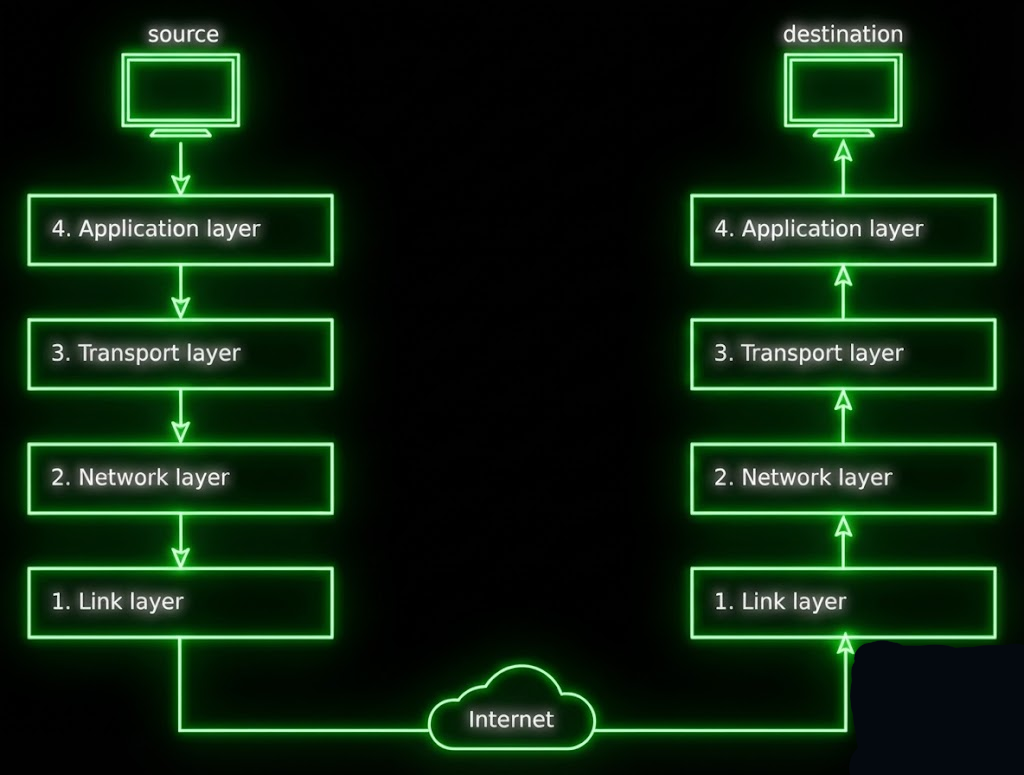
In this blog post, I will take you through the journey of a packet up through the TCP/IP stack, out over a wireless interface. I would highly recommend reading the paper mentioned above for a more detailed understanding of overview of the TCP/IP stack and basic egress and ingress packet flow.
Hardware and Software Setup #
TCP IP Stack #
FOr this I am using an Raspberry Pi Zero 2W with Embedded Linux running on it to keep into the world of embedded systems. As the blog post journey progress I will be compiling custom kernel to log, display a packet flow through the stack. The RPi Zero 2W has a built-in wireless interface that I will be using to send and receive packets.
Knowlege of basic TCP/IP stack is assumed to follow this blog post.
And knowledge of basic packet structure is also required. See wikipedia articles on TCP and IP.
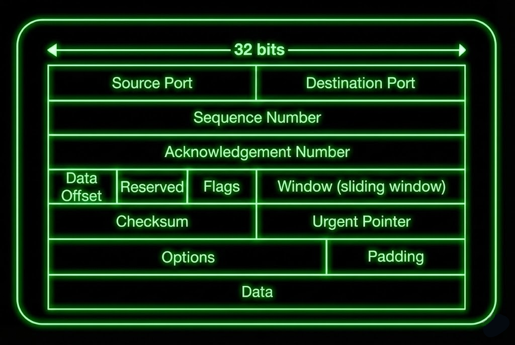
TCP Header (IPv4) #
To jog your memory here is the TCP header structure [5].
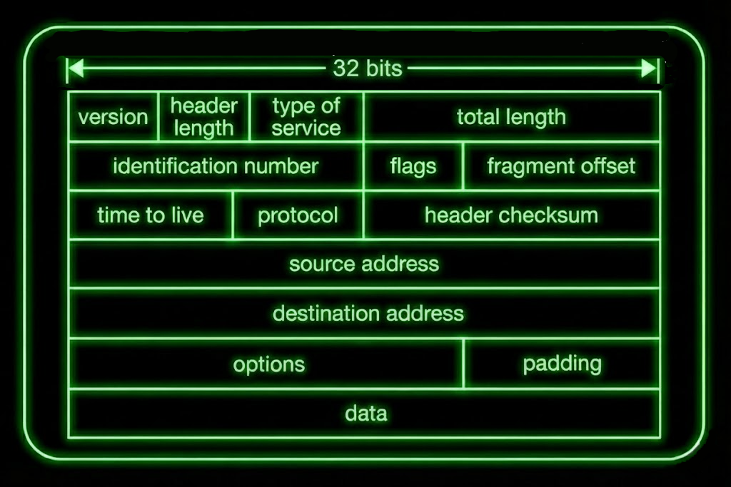
IP Header (IPv4) #
and here is the IP header structure [2].
I will be using Raspberry pi kernel form github repo LINK and specifically commit id a1073743767f9e7fdc7017ababd2a07ea0c97c1c which is version 6.12.y.
As kernel is very dynamic and changes often, I will be using this specific commit id to ensure that the code snippets and file paths and line number mentioned in this blog post are consistent and easily verifiable.
I will start by going from the bottom of the stack to the top of the stack for ingress packet flow.
Physical Layer (Wireless Interface) #
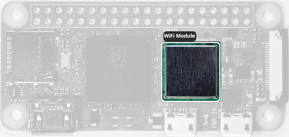
Before we understand how a packet is processed by the TCP/IP stack, we need to understand how the packet is received by the physical layer. In our case, the physical layer is the wireless interface on the RPi Zero 2W. The wireless module on RPi is not completely open source. The wireless module firmware is closed source and is provided by Broadcom. However, the driver for the wireless module is open source and is part of the Linux kernel.
Also it claimed to be using SYN43436 chip for wireless communication made by Synaptic as described in the blog by Jeff Geerling LINK.Also the availabity of complete schematic for the RPi Zero 2W is limited. There are some reduced schematics available from Raspberry Pi foundation LINK but they do not include the wireless module details.
There is reverse engineered schematic available LINK but it is not official and might contain errors. Intrestingly, it is also to be noted that this schematic assumes it to be CYW43438 wireless chip manufactured by Infineon. Though the make of the chip doesnt concern us much as we are more interested in how the packet is processed by the TCP/IP stack. What we need to know is how the data is communicated between the wireless module and the main processor.
SDIO Interface #
The wireless module communicates with the main processor over SDIO interface. The SDIO interface is a standard interface for communication used in many embedded application as protocol to communicate with SD cards but an extended version of it is used to communicate with wireless modules or any other peripheral devices if it supports SDIO protocol.
When a packet is received by the wireless module, it is processed by the wireless module and then passed to the driver over the SDIO interface. The driver then processes the packet and passes it to the network stack.
The specific command of the SDIO interface used to receive the packet is SDIO CMD53 which is anIO_RW_EXTENDED command to read multiple bytes of data from the wireless module. The driver uses this command to read the packet data from the wireless module and then passes it to the network stack.
The SDIO interface is well documented in the SDIO specification which is available on the SD Association website.
SDIO CMD53: is transmitted as a 48-bit frame on the SDIO bus:
SDIO Protocol (48 bits):
┌──┬──┬────────┬──────────────────────────────────┬────────┬──┐
│ST│TR│ Index  │         Argument                 │  CRC7  │ET│
│  │  │(6 bits)│        (32 bits)                 │(7 bits)│  │
└──┴──┴────────┴──────────────────────────────────┴────────┴──┘
 1  1     6              32                          7      1
         CMD53=0x35      (function, addr, etc.)

ST - Start Bit (always 0)
TR - Transmission Bit (1 for host to card, 0 for card to host)
Index - Command Index (CMD53 = 0x35)
Argument - Command Argument (function number, address, block mode, etc.)
CRC7 - 7-bit CRC for error checking
ET - End Bit (always 1)
CMD53 Argument Format #
The 32-bit argument field for CMD53 is structured as follows:
┌──────┬──────────────┬──────────────┬──────────────┬────────────────┬──────────────┐
│ 31   │30          28│27            │26            │25            9 │8           0 │
├──────┼──────────────┼──────────────┼──────────────┼────────────────┼──────────────┤
│R/W   │Function Num  │Block Mode    │OP Code       │Register Address│Byte/Block    │
│(1bit)│(3 bits)      │(1 bit)       │(1 bit)       │(17 bits)       │Count (9 bits)│
└──────┴──────────────┴──────────────┴──────────────┴────────────────┴──────────────┘
Bit 31: R/W Flag
0= READ from card to host1= WRITE from host to card
Bits 30-28: Function Number (3 bits)
- Values: 0-7
- Selects which SDIO function to access
- For WiFi module:
000(0) = Function 0 (CCCR/common registers)001(1) = Function 1 (control registers)010(2) = Function 2 (data/WiFi packets) ← Most common for packet data
Bit 27: Block Mode
0= Byte mode - transfer arbitrary bytes (1-512)1= Block mode - transfer in fixed block sizes
Bit 26: OP Code (Address Increment)
0= FIFO mode - fixed address (read same register repeatedly)1= Increment mode - auto-increment address after each transfer
Bits 25-9: Register Address (17 bits)
- Range:
0x00000-0x1FFFF(128KB address space) - The starting address for the transfer
- For FIFO operations, typically
0x0000
Bits 8-0: Count (9 bits)
- Range: 0-511
- In Byte Mode: Number of bytes to transfer (1-512, where 0 means 512)
- In Block Mode: Number of blocks (1-511)
- Total bytes = count × block_size
- Example: count=2, block_size=64 → 128 bytes total
IO_RW_EXTENDED command (CMD53) #
In order to read and write multiple I/O registers with a single command, a new command, IO_RW_EXTENDED is defined in SDIO protocol. This command is included in command class 9 (I/O Commands).
This command allows the reading or writing of a large number of I/O registers with a single command. Since this is a data transfer command, it provides the highest possible transfer rate. The response from the SDIO card to CMD53 will be R5 (the same as CMD52). For CMD53, the 8-bit data field will be stuff bits and shall be read as 0x00.
CMD53 Data Transfer Format #
When executing the IO_RW_EXTENDED (CMD53), the multi-byte or multi-block data transfer is similar to the data transfer for memory. For the multi-byte transfer modes (block mode=0) the following applies:
- IO_RW_EXTENDED byte read is similar to
CMD17 (READ_SINGLE_BLOCK) - IO_RW_EXTENDED byte write is similar to
CMD24 (WRITE_BLOCK)
Note that the byte count for this transfer is set in the command, rather than the fixed block size. Thus, the size of the data payload will be in the range of 1-512 bytes.
The block mode is similar to the following memory commands:
- IO_RW_EXTENDED block read is similar to
CMD18 (READ_MULTIPLE_BLOCK) - IO_RW_EXTENDED block write is similar to
CMD25 (WRITE_MULTIPLE_BLOCK)
For the block mode the only difference is that for a fixed block count, the host does not need to stop the transfer, as it will continue until the block count is satisfied. If the block count is set to zero, the operation is identical to the memory mode in that the host must stop the transfer.
Wireless Module SDIO Architecture and Control flow #
The architecture of the SDIO interface between the wireless module and the main processor is shown below. The wireless module has an SDIO controller that communicates with the main processor over the SDIO interface.
The SDIO controller has multiple I/O functions that are used to communicate with the main processor.

Wireless Module to Host Communication Flow:*
- WiFi chip’s radio receives a wireless frame (802.11)
- Firmware running on the chip:
- Demodulates and decodes the frame
- Performs MAC layer processing
- Buffers the frame in internal memory
- Updates status registers
- Firmware asserts an interrupt to notify the host
- This can be via Intrrupt GPIO line or SDIO DAT1 line interrupt:
- Out-of-Band (OOB) GPIO line
- In-Band SDIO DAT1 line interrupt
- This can be via Intrrupt GPIO line or SDIO DAT1 line interrupt:
In Raspberry Pi Zero 2W, the wireless module uses the In-Band SDIO DAT1 line interrupt to notify the host when a packet is received. The host then reads the packet data from the wireless module using the SDIO CMD53 command.
The pin connection can be seen in the reverse engineered schematic mentioned above. The SDIO interface pins are connected to the main processor as shown below.
The interface can also be verified by device tree file located at arch/arm/boot/dts/bcm2710-rpi-zero-2-w.dts in the kernel source code. The pin used are GPIO 34 to GPIO 39 for SDIO interface as ALT3 function. If you want to know more about Raspberry Pi pin multiplexing and alternate functions please refer to Raspberry Pi GPIO documentation.
	sdio_pins: sdio_pins {
		brcm,pins =     <34 35 36 37 38 39>;
		brcm,function = <7>; // alt3 = SD1
		brcm,pull =     <0 2 2 2 2 2>;
	};
You may also find the driver used :
&mmcnr {
	pinctrl-names = "default";
	pinctrl-0 = <&sdio_pins>;
	bus-width = <4>;
	status = "okay";
	#address-cells = <1>;
	#size-cells = <0>;

	brcmf: wifi@1 {
		reg = <1>;
		compatible = "brcm,bcm4329-fmac";
	};
};
As you see the driver used is brcmfmac which is the Broadcom FullMAC wireless driver for Linux. This driver is responsible for communicating with the wireless module over the SDIO interface and passing the packet data to the network stack.
Packet Reception at Physical Layer #
When a packet is received by the wireless module, the following steps occur to process the packet and pass it to the network stack:
- The wireless module receives the packet over the air and processes it using its internal firmware.
- The firmware buffers the packet in its internal memory and updates the status registers.
- The firmware asserts an interrupt at GPIO/SDIO DAT1 line to notify the host that a packet is available.
- The host CPU receives the interrupt and the
brcmfmacdriver is notified. - The driver uses the
SDIO CMD53command to read the packet data from the wireless module.
Lets see the relevant code in the driver section that handles the interrupt and reads the packet data.
Tracing the brcmfmac Driver #
The brcmfmac driver provides tracing functionality that can be enabled to log the packet flow through the driver. The tracing can be enabled by setting the brcmfmac debug level to TRACE using the following command:
# Flags breakdown:
# 0x00000002 - TRACE  (function entry/exit)
# 0x00000008 - DATA   (data path)
# 0x00000080 - BYTES  (hexdump)
# 0x00000100 - INTR   (interrupts)
# 0x00000200 - GLOM   (glomming)
# 0x00020000 - SDIO   (SDIO operations)

echo 0x0002038A | sudo tee /sys/module/brcmfmac/parameters/debug
will enable tracing for Ingress packet flow. As sson as I enable this I can see all the packet flow logs in the kernel log using dmesg command. As shown below:
$ dmesg | grep brcmfmac
[  786.309240] brcmfmac: brcmf_netif_rx rx proto=0x800
[  786.309345] brcmfmac: brcmf_sdiod_recv_pkt addr = 0x18000000, size = 64
[  786.309425] brcmutil: RxHdr:
[  786.309440] 00000000: 00 00 00 00 00 00 00 00 00 00 00 00              ............
[  786.309458] brcmfmac: brcmf_sdio_readframes processed 1 frames
...
...
Only catch is the kernel should be compiled with CONFIG_BRCMDBG=y in the kernel config file located at /boot/config-$(uname -r).
If not you can recompile the kernel with this option enabled.
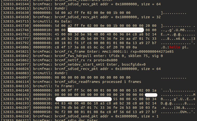
I could see the packet flow logs in the kernel log. Now lets see the relevant code in the driver that handles the interrupt and reads the packet data. I sent hello pi packet from another machine to the RPi Zero 2W and captured the packet flow in the kernel log.
nc -l 2424 &
From another machine I sent the packet using netcat command.
echo "hello pi" | nc <rpi_zero_2w_ip> 2424
On the RPi Zero 2W I could see the packet flow in the kernel log as shown above.
sudo dmesg | tail -500 |grep -C 100 hello
The hidden part is my MAC address.
Understanding the Packet Reception Log #
Let’s break down what’s happening in the captured kernel log when the “hello pi” packet arrives at the RPi Zero 2W.
The Wi-Fi Chip Signals Data Arrival #
The Wi-Fi chip signals that it has data for the host. Module raises a SDIO interrupt to notify the host CPU that a packet is available to read on GPIO/SDIO DAT1 line.
The interrupt is handled by sdhhci driver which is part of the mmc subsystem in the Linux kernel.
The interrupt is handled by the sdhci_irq function located at drivers/mmc/host/sdhci.c line 3526 in the kernel source code. The function is called when an interrupt is received from the SDIO interface. If you are wondering where it is registered, it is registered in the sdhci_add_host function located at drivers/mmc/host/sdhci.c line 4910. This is regestered during the initialization of the SDIO host controller when kernel boots and parse the device tree file.
So the DAT1 pin is the physical interrupt line and processor asserts it, SDHCI driver detects it. Interrupt is disabled immediately this prevents interrupt storm while processing and the Driver re-enables after reading packet to allows next packet interrupt.
static irqreturn_t sdhci_irq(int irq, void *dev_id)
{
    // 1. Read interrupt status register
    intmask = sdhci_readl(host, SDHCI_INT_STATUS);

    // 2. Loop through interrupt handling
    do {
        // Process other interrupts (CMD, DATA, etc.)
        // 3. Check For SDIO WiFi Interrupt
        if ((intmask & SDHCI_INT_CARD_INT) &&     // bit 8 set?
            (host->ier & SDHCI_INT_CARD_INT)) {   // interrupt enabled?

		if (intmask & SDHCI_INT_CMD_MASK)
			sdhci_cmd_irq(host, intmask & SDHCI_INT_CMD_MASK, &intmask);

		if (intmask & SDHCI_INT_DATA_MASK)
			sdhci_data_irq(host, intmask & SDHCI_INT_DATA_MASK);


            // 4. Disable Interrupt (prevent storm)
            sdhci_enable_sdio_irq_nolock(host, false);
            ...
            ...
            // 5. Signal MMC Core (queue work)
            sdio_signal_irq(host->mmc);
        }

        // 6. Check for more interrupts
        intmask = sdhci_readl(host, SDHCI_INT_STATUS);
    } while (intmask && --max_loops);

    return IRQ_HANDLED;
}
As we can see this is common code for SD Cards or other devices using SDIO interface but the key part is how it handles the SDIO interrupt for WiFi module.
SDIO Interupt #
This is the most important part for WiFi!
The WiFi module asserts the SDIO interrupt line (DAT1) to signal “I have data for you”. Disables interrupt for sometime.Calls sdio_signal_irq() to wake the WiFi driver thread to read the pending data. As we cannot immidetly process the data in interrupt context often it is slow to read data over SDIO interface. So the actual data read is deferred to a workqueue/thread context. which is handled by the sdio_run_irqs which inturn calls process_sdio_pending_irqs in later part of the driver.
if ((intmask & SDHCI_INT_CARD_INT) &&
    (host->ier & SDHCI_INT_CARD_INT)) {
    sdhci_enable_sdio_irq_nolock(host, false);
    sdio_signal_irq(host->mmc);
}
Command Completion #
The key part here is:
if (intmask & SDHCI_INT_CMD_MASK)
sdhci_cmd_irq(host, intmask & SDHCI_INT_CMD_MASK, &intmask);
Handles completion of SDIO commands. For WiFi: CMD52: Single-byte I/O register access (WiFi control registers) CMD53: Multi-byte block transfers (WiFi packet data)
Data transfer completion #
if (intmask & SDHCI_INT_DATA_MASK)
sdhci_data_irq(host, intmask & SDHCI_INT_DATA_MASK);
Processes data phase interrupts. When your WiFi module sends/receives a packet via CMD53, this handles:
DMA completion Buffer boundaries Transfer errors
the sdhci_readl is helper read memory function to read the SDHCI_INT_STATUS register to get the interrupt status.
If you dig deaper you will reach to following function:
#ifndef __raw_readl
#define __raw_readl __raw_readl
static inline u32 __raw_readl(const volatile void __iomem *addr)
{
	return *(const volatile u32 __force *)addr;
}
#endif
Offcourse the actual read has some checks and bounds that are omitted here for brevity.
After the sdio_signal_irq function is called, the mmc core is notified which in turn calls process_sdio_pending_irqs. The process_sdio_pending_irqs function in turn calls brcmf_sdio_irq function in the brcmfmac driver to handle the interrupt with the hepl of bunch of helper function like brcmf_ops_sdio_interrupt and brcmf_sdiod_ib_irqhandler().
If you are wondering how process_sdio_pending_irqs knows about brcmf_sdio_irq, it is registered as part of the sdio driver initialization when the driver is loaded during kernel boot.
nt brcmf_sdiod_intr_register(struct brcmf_sdio_dev *sdiodev)
{
    struct brcmfmac_sdio_pd *pdata;
    pdata = &sdiodev->settings->bus.sdio;

    if (pdata->oob_irq_supported) {
        // Use Out-of-Band GPIO interrupt
        brcmf_dbg(SDIO, "Enter, register OOB IRQ %d\n", pdata->oob_irq_nr);
        ret = request_irq(pdata->oob_irq_nr, brcmf_sdiod_oob_irqhandler, ...);

    } else {
        // Use SDIO In-Band interrupt
        brcmf_dbg(SDIO, "Entering\n");

        // Register interrupt handler for Function 1
        sdio_claim_irq(sdiodev->func1, brcmf_sdiod_ib_irqhandler);
        //                             ^^^^^^^^^^^^^^^^^^^^^^^^^^^
        //                             This is the in-band handler!

    }

    return 0;
}
BRCMF Driver #
As we have reached the brcmfmac driver code, brcmf_sdio_isr queues the interrupt handling work to be processed in thread context. Now depeding on if SDIO bus is sleeping or not it uses different functions to read the packet data from the wireless module.
if the bus is sleeping we request to wake the bus brcmf_sdio_bus_sleep(). After the bus is awake we read the Frame header in brcmf_sdio_readframes which reads the packet data using SDIO CMD53 command in brcmf_sdiod_recv_pkt function. There is also something called glomming which is used to read multiple packets in a single CMD53 command to improve performance. I am not going into details of glomming here as it is out of scope for this blog post.
I have created a sequence diagram w.r.t the packet reception flow as seen in log above. Right click and view in another tap to see full size.

If you look into the logs carefully you will see the following RxHdr:
brcmutil: RxHdr:
00000000: 5d 00 a2 ff 51 02 00 0e 00 02 00 00              ]...Q.......
In the logs we see we are reading 64 bytes from address 0x18000000 using SDIO CMD53 command. The first 12 bytes are the frame header as shown below:
If you look at previous section SDIO Interface you will see the structure of SDIO CMD53 command argument. The brcmf_sdiod_skbuff_read which wraps mmc_io_rw_extended function constructs the CMD53 command and argumenta to read the packet data from the wireless module.
The brcmf_sdiod_recv_pkt function reads the packet data from the wireless module using SDIO CMD53 command.
int brcmf_sdiod_recv_pkt(struct brcmf_sdio_dev *sdiodev, struct sk_buff *pkt)
{
	u32 addr = sdiodev->cc_core->base;
	int err = 0;

	brcmf_dbg(SDIO, "addr = 0x%x, size = %d\n", addr, pkt->len);

	err = brcmf_sdiod_set_backplane_window(sdiodev, addr);
	if (err)
		goto done;

	addr &= SBSDIO_SB_OFT_ADDR_MASK;
	addr |= SBSDIO_SB_ACCESS_2_4B_FLAG;

	err = brcmf_sdiod_skbuff_read(sdiodev, sdiodev->func2, addr, pkt);

done:
	return err;
}
This has two parts one is setting the backplane window using brcmf_sdiod_set_backplane_window function and then reading the packet data using brcmf_sdiod_skbuff_read function. The brcmf_sdiod_skbuff_read function uses SDIO CMD53 command to read the packet data from the wireless module.
Think Backplane Window as a way to access different sections of the WiFi chip’s memory. Since the chip has a lot of memory, we can’t access it all at once. Instead, we set a “window” to focus on a specific part of the memory we want to read from or write to.
The function maps a 32-bit chip address into the limited SDIO address window so the host can access it via SDIO Function 1.
If you want to access address 0x18000100:
- Window base =
0x18000000(upper bits, SBSDIO_SBWINDOW_MASK) - Offset =
0x00000100(lower bits, SBSDIO_SB_OFT_ADDR_MASK) - Function programs window registers to point to
0x18000000 - Then accesses SDIO address
0x8100(Offset0x100|SBSDIO_SB_ACCESS_2_4B_FLAG0x8000) which maps to chip address0x18000100
Now this address 0x18000000 is the base address of the wireless module’s core (accessed via SDIO function 1 for control/register access). However, the actual packet data is read from SDIO function 2, which is dedicated to data transfer. The address is calculated by setting the backplane window to point to the wireless module’s memory region and then adding the appropriate offset.
The address in our case points to the FIFO buffer of the wireless module where the received packet is buffered. Looking at the code, we can see that brcmf_sdiod_recv_pkt uses sdiodev->func2 (line 340 of drivers/net/wireless/broadcom/brcm80211/brcmfmac/sdio.c), confirming that packet data is read from function 2, while function 1 is used for control operations like setting the backplane window in brcmf_sdiod_set_backplane_window.
mmc_io_rw_extended(func->card, write,
				func->num, addr, incr_addr, buf,
				blocks, func->cur_blksize);
From mmc_io_rw_extended() at lines 136-143:
	cmd.opcode = SD_IO_RW_EXTENDED;
	cmd.arg = write ? 0x80000000 : 0x00000000;
	cmd.arg |= fn << 28;
	cmd.arg |= incr_addr ? 0x04000000 : 0x00000000;
	cmd.arg |= addr << 9;
	if (blocks == 0)
		cmd.arg |= (blksz == 512) ? 0 : blksz;	/* byte mode */
	else
		cmd.arg |= 0x08000000 | blocks;		/* block mode */
	cmd.flags = MMC_RSP_SPI_R5 | MMC_RSP_R5 | MMC_CMD_ADTC;
┌──┬──┬────────┬──────────────────────────────────┬───────┬──┐
│0 │1 │ 110101 │         0x2D000001               │ CRC7  │1 │
└──┴──┴────────┴──────────────────────────────────┴───────┴──┘
 ST TR  CMD53            Argument                  (calc) ET
│   │     │                   │                    │       │
│   │     │                   │                    │       └─ End bit (always 1)
│   │     │                   │                    └─ CRC7 (calculated by hardware)
│   │     │                   └─ 32-bit argument (0x2D000001)
│   │     └─ Command index 53 (0x35 = 0b110101)
│   └─ Transmission bit (1 = host-to-card)
└─ Start bit (always 0)
and we receive the following frame header:
brcmutil: RxHdr:
00000000: 5d 00 a2 ff 51 02 00 0e 00 02 00 00              ]...Q.......
brcmfmac: brcmf_sdiod_recv_pkt addr = 0x18000000, size = 32
brcmutil: Rx Data:
00000000: 5d 00 a2 ff 51 02 00 0e 00 02 00 00 00 00 20 00  ]...Q......... .
00000010: 00 00 xx xx xx xx xx xx yy yy yy yy yy yy 08 00  ..,.g'.U.M0.....
00000020: 45 00 00 3d be a3 40 00 40 06 96 79 c0 a8 b2 14  E..=..@[email protected]....
00000030: c0 a8 b2 38 db b6 09 78 36 fe 26 f9 d7 01 7c 33  ...8...x6.&...|3
00000040: 80 18 01 f6 21 6b 00 00 01 01 08 0a 14 11 e5 73  ....!k.........s
00000050: c8 a3 56 cd 68 65 6c 6c 6f 20 70 69 0a           ..V.hello pi.
brcmfmac: brcmf_rx_frame Enter: mmc1:0001:1: rxp=00000000c2931f44
This is the frame header and data read from the wireless module . The frame header contains information about the packet such as its size, status, and other metadata. The actual packet data follows this header in the buffer read from the wireless module.
SDPCM Header Decode:
| Offset | Bytes | Field | Value | Description |
|---|---|---|---|---|
| 0-1 | 5d 00 | length | 0x005d | 93 bytes total |
| 2-3 | a2 ff | checksum | 0xffa2 | Checksum: ~0x005d (valid) |
| 4 | 51 | sequence | 0x51 | Sequence number = 81 |
| 5 | 02 | channel_flags | 0x02 | Channel 2 (DATA), no GLOM |
| 6 | 00 | next_length | 0x00 | No next frame |
| 7 | 0e | data_offset | 0x0e | Data starts at offset 14 |
| 8-9 | 00 02 | flow/credit | - | Flow control bits |
| 10-11 | 00 00 | reserved | - | Reserved bytes |
┌────────────────────────────────────────────────┐
│ SDPCM Header (12 bytes)                        │
├────────────────────────────────────────────────┤
│ 5d 00 a2 ff 51 02 00 0e 00 02 00 00            │
│ │           │     │     │     └─ Reserved      │
│ │           │     │     └─ Flow control        │
│ │           │     └─ Data offset = 14 bytes    │
│ │           └─ Seq 0x51, Channel 0x02          │
│ └─ Length: 93 bytes, Checksum ~93              │
├────────────────────────────────────────────────┤
│ BDC Header (4 bytes)                           │
├────────────────────────────────────────────────┤
│ 00 00 20 00                                    │
│ Flags: 0x0000, Priority: 0x20, Interface: 0x00 │
├────────────────────────────────────────────────┤
│ Ethernet Frame (77 bytes)                      │
├────────────────────────────────────────────────┤
│ Destination MAC: xx:xx:xx:xx:xx:xx (Your Pi)   │
│ Source MAC:      yy:yy:yy:yy:yy:yy (Sender)    │
│ EtherType:       0x0800 (IPv4)                 │
├────────────────────────────────────────────────┤
│ IP Header (20 bytes)                           │
├────────────────────────────────────────────────┤
│ Version: 4, IHL: 5, Total Length: 61 bytes     │
│ Source IP:      192.168.178.20  (c0 a8 b2 14)  │
│ Destination IP: 192.168.178.56  (c0 a8 b2 38)  │
│ Protocol: 6 (TCP)                              │
├────────────────────────────────────────────────┤
│ TCP Header (32 bytes with options)             │
├────────────────────────────────────────────────┤
│ Source Port:      56246 (db b6)                │
│ Destination Port: 2424  (09 78)                │
│ Sequence:         0x36fe26f9                   │
│ Acknowledgment:   0xd7017c33                   │
│ Flags: PSH, ACK                                │
├────────────────────────────────────────────────┤
│ TCP Data (9 bytes)                             │
├────────────────────────────────────────────────┤
│ 68 65 6c 6c 6f 20 70 69 0a                     │
│ "hello pi\n"                                   │
└────────────────────────────────────────────────┘
The brcmf_sdiod_skbuff_read this is crux of reading a packet and putting it into a socket buffer (sk_buff).
I have not touched sk_buff structure here but that is the fundamental data structure in Linux kernel networking stack to represent a network packet. It is defined in include/linux/skbuff.h.
This structure is where all networking magic happens in Linux kernel. Every packet that is sent or received by the kernel is represented by an sk_buff structure. The sk_buff structure contains all the metadata about the packet such as its length, protocol, source and destination addresses, and other information. In our journy to the application layer we will see how this sk_buff structure is used to pass the packet up the stack. As soon as the packet is read into the sk_buff structure, it is passed to the network stack using brcmf_netif_rx function. You can see the call to bcmf_rx_frame in brcmf_sdio_readframes at the end of the function. I have glossed over some parts for brevity but as the driver is quite complex it would be impossible to cover everything in a single blog post.
Aren’t all drivers made equal? #
Now some curious minds who have read the paper might be asking why I did not talk about ring buffers as the paper beautifully explains with a diagram. Aren’t all drivers made equal? The answer is no. Different drivers have different implementations and different ways of handling packet reception. The brcmfmac driver uses a simpler approach of reading the packet data using SDIO CMD53 command rather than using ring buffers.
The SDIO core works on a request-response model. The driver calls sdio_readsb() or sdio_memcpy_fromio(), and the function splits the transfer into CMD53 commands. Each CMD53 executes synchronously, and data goes directly to or from the caller’s buffer without intermediate ring buffers. Ring buffers are typically used in DMA Push models (like PCIe), where the device writes data into host memory autonomously. SDIO uses a Host Pull model. The host must explicitly ask for the data using CMD53 (IO_RW_EXTENDED).
You might wonder why there is no call to netif_receive_skb() as described in paper rather calles netif_rx() function. The reason lies in the driver’s architecture.it uses workqueues instead of NAPI polling that most modern driver uses. This approach is simple and safe across all contexts. This is why many legacy or simpler WiFi drivers stick with netif_rx() instead of the more modern NAPI approach.
Next Steps #
Our packet has been successfully read from the wireless module and passed to the network stack. In the next blog post, we will see how the packet is processed by the network stack and passed up to the application layer. We will also see how the TCP/IP stack handles the packet and how it is processed by each layer of the stack. Share and stay tuned for the next part of the journey!