The board #
The Arduino Uno Q is new board from Arduino after the acquisition of Arduino by Qualcomm. It combines the popular Arduino Uno form factor with the powerful Qualcomm’s QRB2210 SOC, which is famous Qualcomm’s Dragonwing series. The board is designed for IoT applications, offering built-in Wi-Fi and Bluetooth connectivity, making it ideal for projects that require wireless communication. Previously I was skeptical about this board and thought it would be just another Raspberry Pi style board with fan following among hobby electronics enthusiasts. The reason being “Not so open” nature of Broadcom SOCs used in Raspberry Pi boards. The SOCs used in Raspberry Pi boards are not available for common folks to buy and create custom boards with them. You need to be a big player to get access to these SOCs. Also the datasheets and other documentation are not completely open for public.
And I had same thoughts about Qualcomm SOCs too. But to my surprise, the Qualcomm QRB2210 SOC started popping up for purchase from various distributors like DigiKeY. That opens up a lot of possibilities for hobbyists and small companies to create custom boards and products using this SOC.
The board comes in eMMC storage option of 16 and 32 gigabytes and has 2 and 4 gigs RAM options. And it features dual-band Wi-Fi 5 and Bluetooth 5.1 for wireless connectivity. It can be powered by USB C port and you can also connect a external docker on the same port for Display and other peripherals. One of the highlights is Graphics Acceleration with Adreno 702 GPU provides hardware-accelerated 3D graphics rendering through open-source Mesa drivers. Applications can access GPU acceleration via standard graphics APIs, including OpenGL, OpenGL ES, Vulkan OpenCL. That was my main reason to get this board as I wanted to explore in the future blogs. Arduino provides Brick services for AI models and other jams. To use this board you need to install Arduinos new App Lab software Link. You can also looks in to Bricks documentation to explore more about AI and other services. Link.
Installation #
Bringing up the board is pretty straightforward. You need Arduino App Lab software if you want to go the easy path. The installation of Arduino App Lab is simple. You can download the installer from the link provided above. In Ubuntu [You need version 22.04 and above] you can download the AppImage file and run it directly. Make sure you have given execute permissions to the file before running it.
chmod +x arduino-app-lab-*.AppImage
./arduino-app-lab-*.AppImage
For me I had to install libwebkit2gtk-4.1-0 package to get the AppImage running. Look at the terminal output for missing dependencies and install them using apt.
sudo apt-get install libwebkit2gtk-4.1-0
When you install and run the App Lab you will see the following screen:
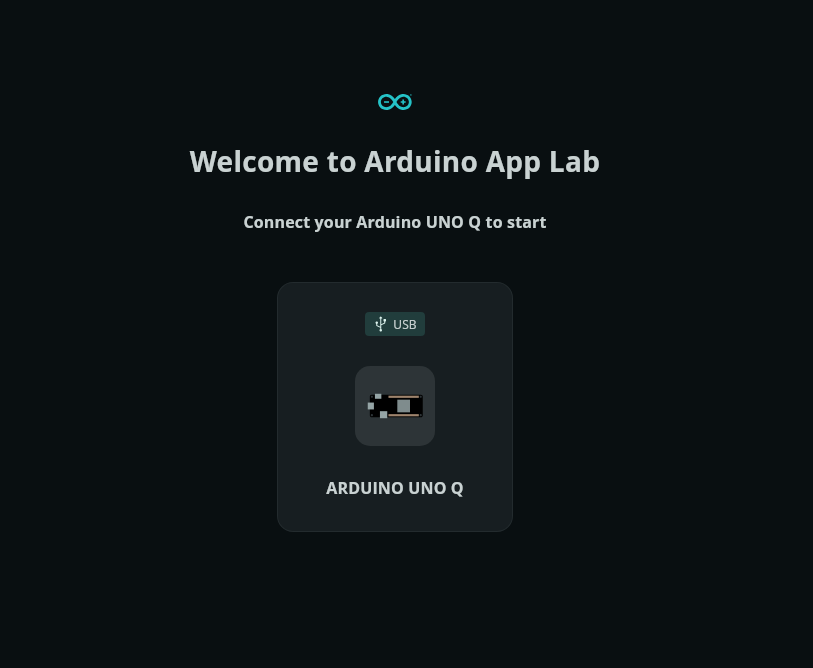
and connect the board using usb and configure the username and password for the board. Once done you can see the board in the left side panel. Also configure the wifi settings to connect the board to internet.you can also use a docker to connect display and ethernet if you have a docker lying around. It seems the board likes some specific dockers and I didnt have luck with it. So I used the USB C connection for power and connectivity over terminal.
If you have the board connected to the wifi network you can ssh into the board using the ip address assigned to it. You can find the ip address from your router or use a network scanner tool like nmap to find the ip address of the board.
The Arduino App Lab might tell you to upgrade the board image. You need to download yet another tool call ed Arduino Flasher CLI to flash the Qualcomm SOCs. You can find the instructions to install and use the tool here. Once you have the tool installed you can use the following command to flash the board.
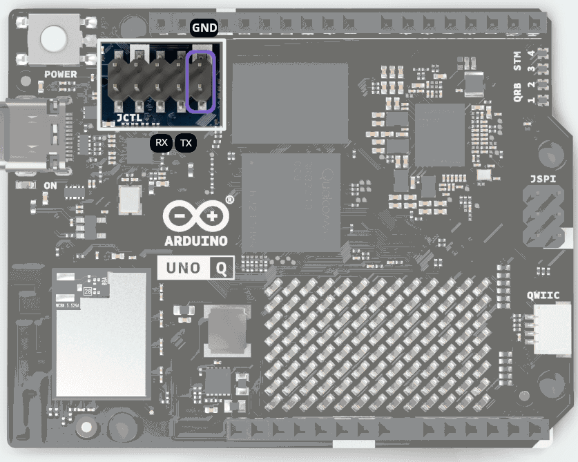
Before flashing you need to set the board in EDL mode. To do that you need to power off the board and connect a jumper between JCTL pins on the board as shown below in violet color:
./arduino-flasher-cli flash latest
it might ask you to download the new release of Debian package for the board. Once the flashing is done you can reboot the board and ssh into it.
Checking for Debian image releases
Found Debian image version: 20251127-441
Do you want to download it? (yes/no)
> yes
if during the flashing process you get stuck at
arduino-unoq-debian-image-20251127-441/disk-sdcard.img.esp
arduino-unoq-debian-image-20251127-441/disk-sdcard.img.root

WARNING: flashing a new Linux image on the board will erase any existing data you have on it.
Do you want to proceed and flash 20251127-441(latest) on the board? (yes/no)
yes
Flashing with qdl
Waiting for EDL device
qdl: unable to open USB device
qdl: unable to open USB device
qdl: unable to open USB device
this is one of the quirks here and indicates that you dont have udev rules setup for the Qualcomm SOC. You can create a udev rule file /etc/udev/rules.d/51-arduino-uno-q.rules with the following content:
vim /etc/udev/rules.d/51-arduino-uno-q.rules
and add following line:
SUBSYSTEM=="usb", ATTR{idVendor}=="05c6", ATTR{idProduct}=="9008", MODE="0666", GROUP="plugdev"
After creating the file reload the udev rules using the following command:
sudo udevadm control --reload-rules
sudo udevadm trigger
Now reconnect the board and try flashing again. It should work this time. You should see the following output:
flashed "BackupGPT" successfully
13 patches applied
partition 0 is now bootable

The board has been successfully flashed. You can now power-cycle the board (unplug and re-plug). Remember to remove the jumper.
You need to setup the username and password again as it is a complete new image. You can use the Arduino App Lab to do that. But I wanted to also look into uart console for debugging and other purposes. So I connected a USB to TTL serial converter to the UART pins on the board. I got the pinout of the board from the schematic provided by Arduino. Here is the schematic snippet showing the JCTL port with UART connection.
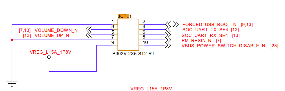
which is mapped to the following pins on the board.
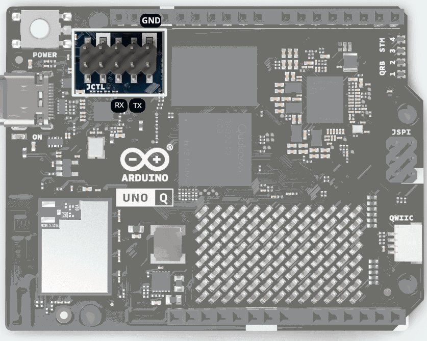
GND pin of the converter to the GND pin of the board. Once connected you can use any serial terminal program like minicom or screen to connect to the board. The default baud rate is 115200. You can use the following command to connect using screen:
minicom -b 115200 -o -D /dev/ttyUSB0
You should see the following output on successful connection as soon as you power on the board:
Welcome to minicom 2.8

OPTIONS: I18n
Port /dev/ttyUSB0, 16:48:53

Press CTRL-A Z for help on special keys


Format: Log Type - Time(microsec) - Message - Optional Info
Log Type: B - Since Boot(Power On Reset),  D - Delta,  S - Statistic
S - QC_IMAGE_VERSION_STRING=BOOT.XF.4.1.2-00023-KAMORTALAZ-5
S - IMAGE_VARIANT_STRING=AgattiPkgLAA
S - OEM_IMAGE_VERSION_STRING=hu-snanaval-hyd
S - Boot Interface: eMMC
S - Secure Boot: Off
...

...
uno-q login: [   21.411867] q6asm-dai ab00000.remoteproc:glink-edge:apr:service@7:dais: DEBUG: q6asm_dai_prepare: pcm size 491520 period 8 period_sz 1920 vs 61440 rate 48000 ch 8
[   21.451621]  MultiMedia1: ASoC: no backend DAIs enabled for MultiMedia1, possibly missing ALSA mixer-based routing or UCM profile
[   21.468317] q6asm-dai ab00000.remoteproc:glink-edge:apr:service@7:dais: DEBUG: q6asm_dai_prepare: pcm size 491520 period 8 period_sz 1920 vs 61440 rate 48000 ch 8
[   21.514687] q6asm-dai ab00000.remoteproc:glink-edge:apr:service@7:dais: DEBUG: q6asm_dai_prepare: pcm size 53760 period 8 period_sz 3360 vs 6720 rate 48000 ch 1
[   21.761698] hdmi-audio-codec hdmi-audio-codec.1.auto: HDMI: Unknown ELD version 0
[   21.842943] hdmi-audio-codec hdmi-audio-codec.1.auto: HDMI: Unknown ELD version 0
[   21.852950] hdmi-audio-codec hdmi-audio-codec.1.auto: HDMI: Unknown ELD version 0
[   33.764979] l5: disabling
[   33.767921] l16: disabling
[   33.771194] usb_vbus: disabling

uno-q login: arduino
Password:
We need to enter arduino as username and it will prompt us to change the password on first login. Once logged in you can use the board like any other Debian based system. You can install packages using apt and explore the board further. Once logged into the shell you can check the board details using the following command:
cat /proc/cpuinfo
cat /proc/meminfo
df -h
this will give you an idea about the hardware specifications of the board.
Fun with GPIOs #
As Hello World of embedded world playing with GPIOs is obligatory.
The Arduino Uno Q board has multiple GPIOs that can be used for various purposes. You can use the GPIOs to interface with sensors, actuators, and other peripherals. The GPIOs can be accessed using the standard Linux sysfs interface. The GPIOs are mapped to the following pins on the board.
The board mapped GPIOs can be found under /sys/class/leds/ directory.
arduino@uno-q:~$ ls /sys/class/leds/
blue:bt  blue:user  green:user  green:wlan  mmc0::  red:panic  red:user
You can control the GPIOs using the echo command. For example, to turn on the red:user LED, you can toggle the trigger file to heartbeat mode using the following command:
echo heartbeat | sudo tee /sys/class/leds/red:user/trigger
similarly I did it for green:user and blue:user LEDs to make a RGB effect on the board.
echo heartbeat | sudo tee /sys/class/leds/green:user/trigger
echo heartbeat | sudo tee /sys/class/leds/blue:user/trigger
And I got the following effect on the board:
Next Steps #
In the folowing blog posts I will explore more about the board and its capabilities. I will also explore the Bricks services provided by Arduino for AI and other applications. Stay tuned for more updates.